STM32F103 Blue Pill Adapter Board (MCU Adaptor Board on the Robot Car)


Soldering Sequence
1. Resistor 100 ohm (R10, R11)
2. Hearder 4-pin right angle (UART1)
3. LED red x 8 pieces (D0 - D7)
4. LED green (B6)
5. Capacitor (C1, C2)
6. Socket 20-pin x 2 pieces (BD1)
7. Socket 4-pin x 2 pieces (J2, J8)
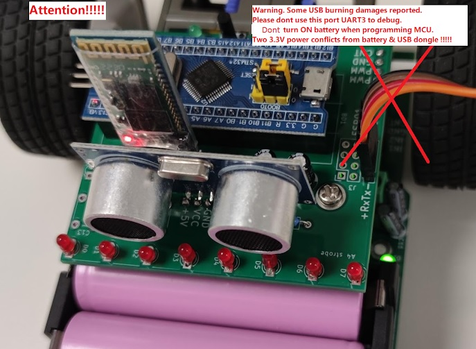
8. Header 4-pin straight (UART3)
9. Tactile switch (A12)
10. Socket, 4-pin x 2pc (J5, J6), 7-pin (J7)


留言
張貼留言