PolyU EIE3105 / EIE3106 Real PCB Photos
2022/2023 S1 to S2 - Integrated Project - Important Note * (15 Mar 2023)
----- ----- * Important Note * ----- -----
Some students reported failure on MCU or USB port burnt in short circuits (pins among 3.3V and GND).
Possible damage causes:
1) The capacitor of C2 on the Blue-Pill MCU adaptor board is too small. It should be 100 uF or larger (recommended to use 220 uF, 10V)
2) Short circuit occured because of bad soldering or wrong connections. Please check your regulator outputs Vcc. It should be 3.3 V.
Is it 3.3 V? Many students reported that the Vcc is 6V to 7V from the 3.3V regulator because it has been burnt due to short circuit. Please don't keep asking for new blue pill MCU board if you haven't checked the Vcc voltage!!! We have purchased many pieces of new AMS1117-3.3V.
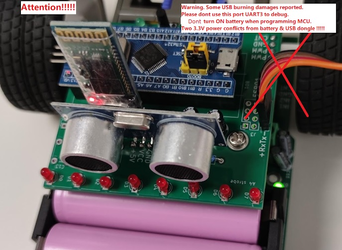
3) The two 3.3V power were turned ON with:
a) Battery power is turned ON to have a regulator to provide 3.3V AND
b) USB port is connected to USB dongle to generate another 3.3V which is conflicting with above 3.3V. These students wanted to connect the debug port UART3.
** Above set-up can cause danger especially when the motors were turned ON which could generate back voltage EMF. So the "3.3V" power pin of the USB debug port must be disconnected. **
Besides, please note that the current red-color USB dongle doesn't have fuse protection. Thus, students are advised to use the Bluetooth module to dump such debug-port data.
You are advised to read the document file attached below:
Download EIE3105 and EIE3106 Hardware Debugging Guideline (2023-Mar-05) (2023-Mar-05)
If you want to use UART3 to debug with RoboCar powered ON (with battery), you MUST disconnect the power pin of the USB dongle. Below is another USB dongle with auto-recover-fuse protection: (note: 3.3V TTL should be chosen)


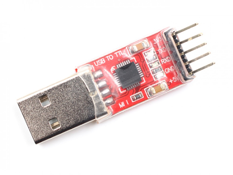
* The
red USB-UART dongle doesn't have fuse protection and the
golden one (
chip CH340G driver) has. The red one can burn your USB port of the PC and burn your RoboCar when you accidentally make some wrong connections. Please use the golden one instead (with the new connection cable).
** Please note that the old red USB-UART dongle should not be used if you experienced blue pill MCU burnt. The red USB dongle will be phased out as it doesn't have protection!!!
We are distributing the new golden-color USB-UART dongle (serial adaptor) (which has short-circuit auto-recover-fuse protection) (more than 100 sets purchased).
Technical support (by Samson, Patrick, and Nick) will be probably provided in the lab CF005 on (every, except holidays) Mondays and Fridays (12.30 to 15:30). The IoT electronic lab (CF005) will be usually open until 18:30.
Please improve the circuit (protection) of the power circuit of the Blue-Pill MCU adaptor board by adding one auto-recover-fuse (0.5A) and one or two 3.9V regulators (in parallel) to the regulator of the blue pill adaptor PCB board. These electronic components can be obtained from Nick, Samson, or Patrick:
----- ----- ----- ----- ----- Lab Info ----- ----- ----- ----- -----
Note of Soldering the Joypad (Joystick PCB with Black-Pill MCU)
for the robot car of the Integrated Project.
Another reference website: EIE Tutor (retired) Mr. SY Lam's Blog: https://ensylam.blogspot.com/
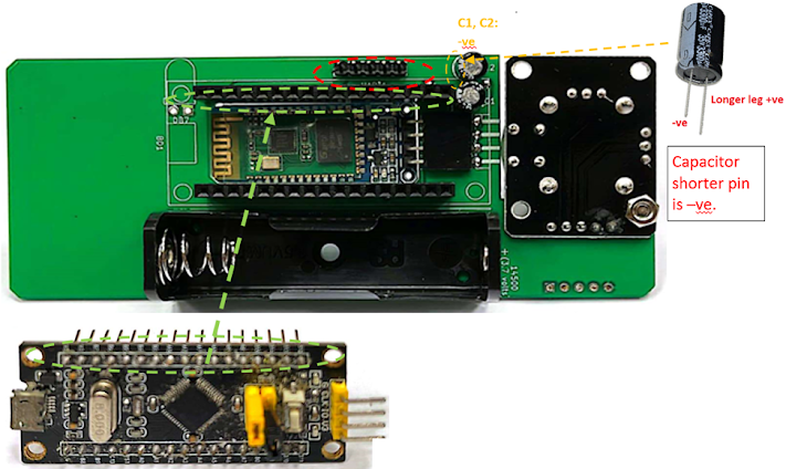
Joypad PCB: D9, D10 diodes. Please note their polarity with the bar indicating negative.
Joypad PCB soldered - TOP side, with joystick module on the left (below photo) with HC06


Please pay attention to the directions of the connectors!!! The Blackpill MCU board should be plugged into the bottom side of the Joypad PCB.
Joypad PCB soldered - BOTTOM side: with HC06
Please check the true real photo first!!!!! 以實物/真實相片的焊接圖為準
Higher resolution photo below:
Soldering Sequence
1. Diode (D9, D10) (note the polarities)
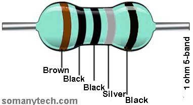
2. Resistor, 1 ohm (R12)
3. Socket 5-pin (J2) solder on the component side
4. Tactile switch (SB5, SB6, SB8, SB9)
5. Socket 4-pin (J1)
6. Capacitor (C1, C2) : max 10V acceptable (please note the polarities)
that might burn the blue pill MCU board.
7. Socket 17-pin x 2 pieces (BD1) (pay attention to the directions of sockets) *焊錯全板會報廢
8. Header 5-pin (UART1)
9. Battery holder (BT1)
10. Joystick + screws + nuts
Color-code of 1 ohm resistors (4-band)
Color-code of 1 ohm resistors (5-band)
Ref.:
ensylam.blogspot.com
To troubleshoot the programming failure by troubleshooting the connections, try to use DMM (Digital Multi-Metter) as shown in the tutorial video in the troubleshooting guide: Place one end to the above connection pin (e.g. Pin A10 on the Black-Pill board) and place another end to the Pin 2 of the UART1 on the JoyPad board, or the TxD on the USB dongle.
----- ----- ----- ----- ----- ----- ----- ----- -----
----- ----- ----- ----- ----- ----- ----- ----- -----
Blue-Pill Adapter Board / CONTROL PCB Board (on Robot Car)
----- Note of soldering -----
D0 to D7 upper position are negative (-ve). Shorter pin of the LED is -ve.
The pins of the LED D0 to D7 are similar. Pin#1 is a square (-ve).
You can look at the die of the LED to identify its positive or negative pin:
Blue-Pill Adapter Board / CONTROL PCB - TOP side:
Blue-Pill Adapter Board / CONTROL PCB - Bottom side
Please check the true real photo first!!!!! 以實物/真實相片的焊接圖為準
Un-assembled PCB Top-side:
Un-assembled PCB Bottom-side:
Schematics page 1:
Schematics page 2:
Blue-pill MCU adaptor board schematics download/open (uploaded in 2023).
Soldering Sequence
1. Resistor 100 ohm (R10, R11)
2. Header 4-pin right angle (UART1)
3. LED red x 8 pieces (D0 - D7) (note the polarities)
4. LED green (B6) (note the polarities)
5. Capacitors (C1, C2) (note the polarities) (10V or 16V ok)
Note: For C2, 100 uF or larger should be used. Smaller values might cause overshoot or transient
6. Socket 20-pin x 2 pieces (BD1) (pay attention to the socket directions *焊錯全板會報廢)
7. Socket 4-pin x 2 pieces (J2, J8)
8. Header 4-pin straight (UART3)
9. Tactile switch (A12) (through-hole one)
10. Sockets, 4-pin x 2 pc (J5, J6), 7-pin (J7)
Color-code of 100 ohm resistors (4-band)
Color-code of 100 ohm resistors (5-band)
Programming the Blue Pill MCU:
To troubleshoot the programming by troubleshooting the connections, try to use one DMM (Digital Multi-Metter) as shown in the tutorial video in the troubleshooting guide: Place one end to the above connection pin (e.g. Pin A10 on the Blue-Pill board) and place another end to the Pin 2 of the UART1 on the Blue-Pill adaptor board, or the TxD on the USB dongle.
----- ----- ----- ----- -----
Robocar / Robo Car:
74HC/HCT299 pdf (Shifting inputs of photoresistors) - HC and HCT differ on voltage input levels
IO0 = Q8, IO1 = Q7, IO2 = Q6, IO3 = Q5, ....., IO7 = Q1
S0 = 1, S1 = MOSI1 = 1 to turn on LEDs (lighting PCB) and load (Qx = IOx: Q7 = IO7, Q6 = IO6 .....)
S0 = 1, S1 = MOSI1 = 0 => Shifting right: DSR → Q0, Q0 → Q1, etc. (MOSI1 at the pin #32 of Blue-pill)
DS0 = 0 = GND, DS7 = 1 always, Q0 = NC, Q7 = MISO1 (Pin #5 of J7) (Blue-pill pin #31)
CP (shift clock by MCU) = SCK1 (Pin #30 of Blue-pill MCU, low-to-high edge trigger)
Robot Car - TOP view
* Attention: the above photo is showing the sockets J5, J6, and J7 with long-pin headers placed on the top so as to connect the MCU blue-pill-adaptor PCB (above the sockets). The sockets (J5 - J7) should be soldered (NOT headers).
Robot Car - Bottom view
Reference of driver IC: (H-bridge motor driver)
Soldering Sequence
- Resistor 560 ohm (R20)
- Green LED 3mm (D1)
- Photo-interrupters (U1, U2). They are in opposite orientations. Datasheets: KTIR0511S
- Capacitors (C6, C10,C11,C12) (10V or above)
- Sockets 4-pin (J5, J6), Socket 7-pin (J7) (sockets are female; long-pin headers are male)
- Terminal blocks (J3, J4). Beware of the orientation.
- Battery holder. Check orientation (small holes on PCB to ensure correct position)
- Switch 3-pin MTS-102 (3P2T)
Photo-interrupters U1, U2
Other modules
- Ball caster
- Infra-red light panel PCB (using M3 x 8 screws)
- Gear-box (38.2:1). Using two drilled gears in place of photo-interrupters (U1, U2).
Note: Must use the
drilled gears so as to allow the photo-interrupters to determine the speed of the rotation.
Photo: Non-drilled gear (left); Drilled gear (right) with holes
Note: the holes are used with photo-interrupters so as to determine the rotation speed or rotation counters.
Gearbox with one drilled gear to be replaced in (2).
Wires connecting the motors to PCB
- AWG#20 wires x 4 (Connecting to the motors)
- Each is about 40mm long (length)
- For the end connecting to the motor: stripped 2mm and tinned
- For the end connecting to the terminal block: stripped 5mm, do not tin.
- Solder wires to the tabs of the motor. There is no need to push the wire into the eyelet of the tab.
Wheel
The construction of the wheels is different from the illustration provided by the vendor. Please refer to the sample given.
Mounting post for Control Board
- M3 x 10 screw + nut
- brass post M3 x 25
----- ----- ----- ----- -----
Test Programs
There are instructions in the readme.md file:
Test Programs to verify the hardware functionality
## ***** Upload program to stm32 boards via UART1 ##
1. DO NOT plug the USB2TTL module into the computer until the wiring is set up properly.
2. Connect your stm32 board to a USB2TTL module. Make sure to use the "3.3V" line on your USB2TTL module. This "3.3V" line shall be connecting to the "+" terminal of the UART1 port.
3. Set the stm32 board to "bootloader" mode by positioning the black jumper cap as shown. (bb) black cap, (yy) yellow cap, (x) unused pin.
4. Plug the USB2TTL module into the computer. The power indicator on the stm32 board shall light. If not, resolder your board.
5. Check the com port number assigned to your USB2TTL in "Device Manager". Use it to upload the test program.
6. Upload the test program using "stm32flash" in "command prompt". Your COM port may vary.
stm32flash is a flash program for STM32 MCU to upload your program using the built-in serial bootloader over UART. The jumpers should be set at boot mode when the stm32flash.stm32flash -b 115200 -w file.hex -v -g 0x0 COM6stm32flash -b 115200 -w blue.hex -v -g 0x0 COM6stm32flash -b 115200 -w joypad.hex -v -g 0x0 COM8
Change COM6 to whatever port you are using. "-g 0x0" means run the program after flashing. Omit it when your program is driving the right wheel because UART 1 share a pin with TIMER 1. Remember to detach the USB2TTL as well.
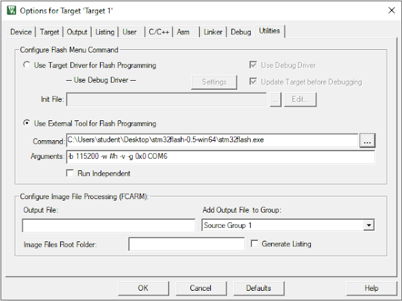
Make sure "file.hex" is generated by checking the appropriate box in "Options for Target":
You can run stm32flash in keil uvision 5 by setting the external tools:
"#h" is the substitution of hex file name.
Remind you once again. Use the 3.3 volts line on the USB2TTL. Never connect the 5 volts line to the robot car.
stm32flash uses SPACE as a delimiter. Therefore your project name and folder name shall not contain SPACE. Chinese characters shall be avoided.
# joypad.hex
1. Data in text format are sent to PC via UART1 with a baud rate 115200.
2. Data in binary format are sent to the Bluetooth (BT) module (HC06) with a baud rate 115200.
# blue.hex
1. Data in text format are sent to PC via UART3 with a baud rate 115200.
2. Binary data are received from the Bluetooth module (HC05) with a baud rate 115200.
3. Whatever is read by the path-finder is displayed at the 8 pieces of red LEDs.
4. Hit the button to change the motor state:
|motor state|
|:---|
|OFF | (Sensor sensing the black line, with red LEDs indicating)
|FAST FORWARD for 1 second (both motors with same PWM rates)|
|SLOW FORWARD|
|ROTATE LEFT|
|SLOW backward|
|ROTATE RIGHT|
Bluetooth (BT) modules: HC-05 vs HC-06
Note: The Bluetooth (BT) modules provided to students were already paired. Baud rate is 115200
| HC-05 | HC-06 |
| master or slave | slave only |
| Enter AT mode (How) | Hold the button while powering up | When powered up, before pairing succeeded |
| Default Baud rate (AT mode) | 38400 | 9600 |
| Send command | Carriage return(enter) and line feed(ctrl-J) after command | The whole command must be sent at once. Recommend pasting the command to the terminal. Neither carriage return nor line feed is needed. |
| Set name to name | AT+NAME=name | AT+NAMEname |
| Set password to 1234 | AT+PSWD=“1234” | AT+PIN1234 |
| Set master | AT+ROLE=1 | (no need to set) Slave mode only |
| Set baud rate to 115200 | AT+UART=115200,1,0 | AT+BAUD8 |
* Note: HC05 is placed at Robot Car; HC06 is at Joypad
More info is at:
(copy to notepad and paste the commands in Tera Term with USB-TTL dongle. Using mouse’s right-click to paste the commands in command prompt) - Below are example AT commands to set the modules respectively:
(at HC-06 side with a PC / Arduino serial)
minicom -b 9600 (default baud rate is 9600, configured by factory)
AT+NAME230305s1505
AT+PIN1234
AT+BAUD8
�
(at HC-05 side with a PC / Arduino serial)
minicom -b 38400 (default baud rate is 38400, configured by factory)
AT+NAME=230305s1505
AT+ROLE=1
AT+PSWD="1234"
AT+NAME?
AT+UART=115200,1,0
Note: above examples are using the same name "230305s1505" (changing them with other names to avoid pairing conflicts with your classmates)
Note as shown on the PCB: "+" = Vcc, "-" = Gnd (HC05)
RoboCar with BT module (left), full set, photos: with HC05 plugged:
BT module on the left and Ultrasound module plugged on the right
LED Lighting Schematics Picture: (SMT assembled by factory)
Schematics (in high resolutions)
---------------------------------------------
(5)
Other info:
Blue-Pill MCU Board (above) - used in RoboCar
Black-Pill MCU Board (above used in JoyPad)
RoboCar with a card-roll at its front:
Blue Pill MCU CH32F103CT8 China-MCU-version:
taobao linkChina-made-version info:
EIE Department
EIE3105 / EIE3106


留言
張貼留言