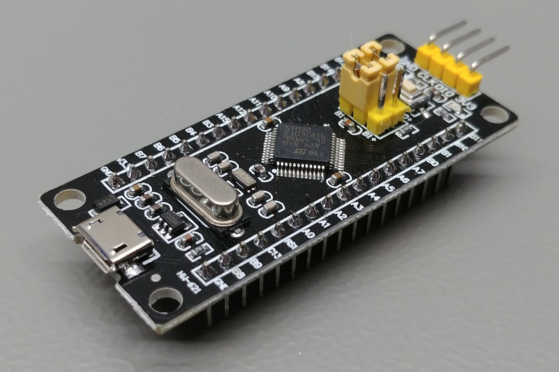
STM32F103 Black Pill (MCU Board of JoyPad)
Component Order in Soldering

1) right angle header
2) 3-pin headers
3) 17-pin headers (fixture required)
MCU Pinouts
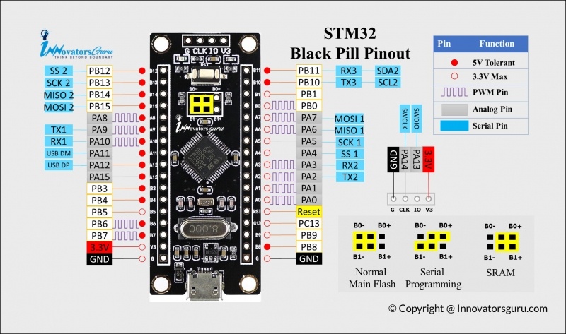
The on-board LED is connected to PB12. Pull it LOW to turn it on.
It can be programmed either through the 4-pin header or through UART1. To program through UART1, set the jumpers to SERIAL PROGRAMMING before powering up. Normally the jumpers should be set in NORMAL MAIN FLASH.
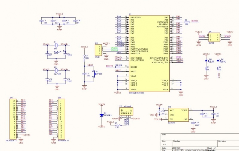
Schematic

留言
張貼留言