Programming The Robot Car

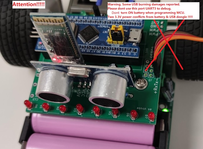
When connecting the USB2TTL to the control board, NEVER USE THE 5 VOLT LINE. It will burn the microcontroller. You must not power up the control board (inserting USB2TTL to PC will power up the 3.3 volt line) unless all connections are properly established. That is, connect the USB2TTL to the control board first. Connect the USB2TTL to PC afterward.
Blink the LEDs
There are three controllable LEDs. A blue LED comes with the MCU module. The control board bears a green LED and a yellow LED.
The first program to write is to blink the LEDs in the background and control them in the main() function.
/* main.cpp */
 oi   ai  u  i  e  i   ;      a    ou    o   a e  ei    e  i e     ou     i   u   io
e u   e    a e   O   O     O  A    A      O  };
e u   e   o o      UE    EE    E  O  };
 oi   e   e   o o    e    a e ;

i    ai   oi
   e    UE  O  ;
   ai      ;             ai   o  1  e o   u i   a         i e
   e    EE   O  ;
   ai      ;             a    ou    o  a e  ei    e  i e
   e   E  O   O  ;
   ai      ;
   e    UE   O  A  ;
   ai      ;
   e    EE     O  ;
   ai      ;
   e   E  O    A   ;
    i e  1   ai    ;     a    ou    o  a e  ei    e  i e
}

v  d w  t( ns gn d  nt)    //b ckgr  nd j bs  r  b  ng s rv c d thr  gh th s f nct  n
 n m l d_st t  {  N,  FF, N RM L, F ST, SL W }
 n m l d_c l r { BL  , GR  N, Y LL W }
v  d l d(l d_c l r, l d_st t )

 nt m  n(v  d) {
  l d(BL  ,  N)
  w  t(400)           //w  t f r   s c nd  s ng   400 Hz t m r
  l d(GR  N,  N)
  w  t(400)           //b ckgr  nd j b  r  b  ng s rv c d
  l d(Y LL W,  N)
  w  t(400)
  l d(BL  , N RM L)
  w  t(400)
  l d(GR  N, SL W)
  w  t(400)
  l d(Y LL W, F ST)
  wh l  ( ) w  t(0)   //b ckgr  nd j b  r  b  ng s rv c d
}
Timing will be derived from timer 1. Set timer 1 to overflow at 400 Hz.
/* tim1.cpp */
 i   u e     3  1

  a    i e
 u  i
   i e   oi  ;
   oi   o    oi  ;
  u  i  e  i    i  ;
  i a e
  u  i  e  i    a  ;
}   a i   i e ;

e  e        oi   I 1 U  I   a   e   oi
   I 1      =   I     UI ;
     i e   i  ;
  }

 i e    i e   oi
       A   E   =     A   E    I 1E        A   E   IO  E        A   E   IO AE ;
    IOA      =   a a  a  ;
    IOA      =       a aa;
    IO       =           ;
    IO       =   aaa  a  ;
   I 1   IE  =  I   IE  UIE;
   I 1      = 3;                1      = 7   3 1
   I 1  A   =   999;              5
    I  E a  eI    I 1 U  I    ;
   I 1    1 =  I    1  E ;       i e  o
}

 oi   e   oi  ;

 oi   i e    o    oi
  i    a   ==  i     e u  ;
   a   =  i  ;                       i   i e a    e o  a e e e u e  o  e e e     5
   e   ;
}

 oi   ai  u  i  e  i   i
  i    i   e u    i e   o    ;
  i  =  i e   i  ;
    i e  i  =  i e   i     i e   o    ;
}

# ncl d  <stm 2f 0x.h>

cl ss T m r {
p bl c:
  T m r(v  d)
  v  d p ll(v  d)
   ns gn d  nt t ck
pr v t :
   ns gn d  nt l st
} st t c t m r

 xt rn "C" v  d T M _ P_ RQH ndl r(v  d) {
  T M ->SR &  ~T M_SR_  F
  ++t m r.t ck
  }

T m r::T m r(v  d) {
  RCC-> PB2 NR   RCC_ PB2 NR_T M  N | RCC_ PB2 NR_  PB N | RCC_ PB2 NR_  P  N
  GP   ->CRL   0x 4 44 42
  GP   ->CRH   0x4444 4
  GP  B->CRL   0x42444440
  GP  B->CRH   0x   24 44
  T M ->D  R   T M_D  R_
  T M ->PSC                   // 8 MHz    2/( + )
  T M -> RR   44              //2.  ms
  NV C_ n bl  RQ(T M _ P_ RQn)
  T M ->CR    T M_CR _C N     //t m r  n
}

v  d l d(v  d)

v  d T m r::p ll(v  d) {
   f (l st    t ck) r t rn
  l st   t ck                    //th s l n   nd b l w  r   x c t d  nc   v ry 2.  ms
  l d()
}

v  d w  t( ns gn d  nt  ) {
   f (! ) r t rn t m r.p ll()
    +  t m r.t ck
  wh l  (  !  t m r.t ck) t m r.p ll()
}
Implementation of LED functions.
/* led.cpp */
 i   u e     3  1
e u   e    a e   O   O     O  A    A      O  };
e u   e   o o      UE    EE    E  O  };

  a    e
 u  i
   e    IO    e e    i   ;
   oi   e   e    a e ;
   oi   i  a   oi  ;
  i a e
    IO    e e    a e;
  i    i ;
   e    a e   a e;
  u  i  e  i    e io    ou  ;
}   a i    ue   IO   1      ee    IO        e  o    IOA    ;

 e    e    IO    e e      i
   a e =  ;
   i  = 1     ;
   e  O   ;
}

 oi   e    e   e    a e
    a e =  ;
  i     == O
    i    i  == 1  1    a e      =  i ; e  e  a e       =  i ;
  }
  i     == O
    i    i  == 1  1    a e       =  i ; e  e  a e      =  i ;
  }
  i     ==  O  A    e io  =    ;
  i     ==  A     e io  =    ;
  i     ==   O    e io  =    ;
}

 oi   e    i  a   oi
  i     a e == O    e u  ;
  i     a e == O     e u  ;
  i      ou      e io    e u  ;
   ou   =  ;
  i    a e  O      i    a e      =  i ; e  e  a e       =  i ;
}

 oi   e   oi
    ue  i  a   ;
    ee   i  a   ;
   e  o   i  a   ;
}

 oi   e   e   o o      e    a e
  i     ==   UE    ue  e    ;
  i     ==   EE     ee   e    ;
  i     ==  E  O    e  o   e    ;
}

# ncl d  <stm 2f 0x.h>
 n m l d_st t  {  N,  FF, N RM L, F ST, SL W }
 n m l d_c l r { BL  , GR  N, Y LL W }

cl ss L d {
p bl c:
  L d(GP  _Typ D f*,  nt)
  v  d s t(l d_st t )
  v  d t ct c(v  d)
pr v t :
  GP  _Typ D f *b s
   nt p n
  l d_st t  st t
   ns gn d  nt p r  d, c  nt
} st t c bl  (GP  B,  2), gr  n(GP  B, 6), y ll w(GP   , 0)

L d::L d(GP  _Typ D f *b,  nt p) {
  b s    b
  p n     << p
  s t( FF)
}

v  d L d::s t(l d_st t  s) {
  st t    s
   f (s     N) {
     f (p n     << 2) b s ->BRR   p n   ls  b s ->BSRR   p n
  }
   f (s     FF) {
     f (p n     << 2) b s ->BSRR   p n   ls  b s ->BRR   p n
  }
   f (s    N RM L) p r  d   400
   f (s    F ST) p r  d   200
   f (s    SL W) p r  d   800
}

v  d L d::t ct c(v  d) {
   f (st t      N) r t rn
   f (st t      FF) r t rn
   f (++c  nt < p r  d) r t rn
  c  nt   0
   f (b s -> DR & p n) b s ->BRR   p n   ls  b s ->BSRR   p n
}

v  d l d(v  d) {
  bl  .t ct c()
  gr  n.t ct c()
  y ll w.t ct c()
}

v  d l d(l d_c l r c, l d_st t  s) {
   f (c    BL  ) bl  .s t(s)
   f (c    GR  N) gr  n.s t(s)
   f (c    Y LL W) y ll w.s t(s)
}
Button Switch
A simple way to get rid of key bouncing issue is to poll the switch at intervals greater than bouncing time. 20 milliseconds should be adequate.
/* tim1.cpp */
void led(void), button(void);

void Timer::poll(void) {
  if (last == tick) return;
  last = tick;                   //this line and below are executed once every 2.5 ms
  led();
  button();                      //call button() every 2.5 ms
}
/* button.cpp */
 i   u e     3  1

  a i  i    e  = 1<<12;

 oo   ea   u  o   oi      e u    e ; }
 oi    a   i u e     ea    o   u  o   oo    }

 oi   u  o   oi
    a i  i    ou  ;
  i      ou         e u  ;          ou
   ou   =  ;
  i     =   IOA  I      1  1  ;
  i    e  ==     e u  ;
  o   u  o    e  =    ;             e  u e   e i e   a   o  o
}

# ncl d  <stm 2f 0x.h>

st t c  nt k y

b  l r  d_b tt n(v  d) { r t rn k y  }
v  d __ ttr b t __((w  k))  n_b tt n(b  l) {}

v  d b tt n(v  d) {
  st t c  nt c  nt
   f (++c  nt < 8) r t rn        //c  nt 20 ms
  c  nt   0
   nt k   GP   -> DR & ( << 2)
   f (k y    k) r t rn
   n_b tt n((k y   k))           //l t  s r d c d  wh t t  d
}
Let's verify it by turning off an LED.
/* main.cpp */
void on_button(bool b) {
  if (b) led(BLUE, OFF);
}
USART: print string
Put the initialization codes in tim1.cpp
//
     A  1E   =     A  1E   U A  3E        A  1E   U A   E ;
U A         = 375 ;                   9
U A  3      = 313;                    115
U A       1 = U A  3    1 = U A     1  E   U A     1  E;
  I  E a  eI   U A    I    ;
  I  E a  eI   U A  3 I    ;
U A       1  = U A     1 UE;
U A  3    1  = U A     1 UE;

RCC-> PB  NR   RCC_ PB  NR_ S RT  N | RCC_ PB  NR_ S RT2 N
 S RT2->BRR      0                  // 600
 S RT ->BRR                         //   200
 S RT2->CR     S RT ->CR     S RT_CR _T  |  S RT_CR _R
NV C_ n bl  RQ( S RT2_ RQn)
NV C_ n bl  RQ( S RT _ RQn)
 S RT2->CR  |   S RT_CR _
 S RT ->CR  |   S RT_CR _
Print string in background at ISR level.
/* uart.cpp */
 i   u e     3  1

  a   Ua
 u  i
  Ua   U A      e e         a e =  ;     =  ; }
   oi  i    oi
    i    a e       U A        E
      i
        i          a e     =       ;
        e  e     =  ;
      } e  e  a e    1  =  U A     1   EIE;
    }
  }
   oo    i    o      a
    i         e u    a  e;
        =  ;
     a e    1  = U A     1   EIE;
     e u     ue;
  }
  i    ea   oi
     e u    a e       U A         E    a e        1;
  }
  i a e
   o      a      ;
  U A      e e    a e;
}   a i  ua    U A      ua  3 U A  3 ;

 oo  ua      i    o      a         e u   ua      i     ; }
 oo  ua  3   i    o      a         e u   ua  3   i     ; }
i   ua     ea   oi      e u   ua     ea   ; }
i   ua  3  ea   oi      e u   ua  3  ea   ; }

e  e        oi  U A    I   a   e   oi     ua    i    ; }
e  e        oi  U A  3 I   a   e   oi     ua  3 i    ; }

# ncl d  <stm 2f 0x.h>

cl ss   rt{
p bl c:
    rt( S RT_Typ D f *b) { b s    b  ptr   0  }
  v  d  sr(v  d) {
     f (b s ->SR &  S RT_SR_TX ) {
       f (ptr) {
         f (*ptr) b s ->DR   *ptr++
         ls  ptr   0
      }  ls  b s ->CR  &  ~ S RT_CR _TX
    }
  }
  b  l pr nt(c nst ch r* p) {
     f (ptr) r t rn f ls
    ptr   p
    b s ->CR  |   S RT_CR _TX
    r t rn tr
  }
   nt r  d(v  d) {
    r t rn b s ->SR &  S RT_SR_RXN  ? b s ->DR : -
  }
pr v t :
  c nst ch r *ptr
   S RT_Typ D f *b s
} st t c   rt2( S RT2),   rt ( S RT )

b  l   rt2_pr nt(c nst ch r* p) { r t rn   rt2.pr nt(p)  }
b  l   rt _pr nt(c nst ch r* p) { r t rn   rt .pr nt(p)  }
 nt   rt2_r  d(v  d) { r t rn   rt2.r  d()  }
 nt   rt _r  d(v  d) { r t rn   rt .r  d()  }

 xt rn "C" v  d  S RT2_ RQH ndl r(v  d) {   rt2. sr()  }
 xt rn "C" v  d  S RT _ RQH ndl r(v  d) {   rt . sr()  }
Now let's click the button to say hello. Use keyboard to control LEDs
/* main.cpp */
bool uart2_print(const char*);
bool uart3_print(const char*);
int uart2_read(void);
int uart3_read(void);

int main(void) {
  while (1) {
    wait(0);                   //background jobs need it
    int k = uart2_read();
    if (k == -1) k = uart3_read();
    if (k != -1) {
      switch (k) {
        case 'b': led(BLUE, OFF); break;
        case 'B': led(BLUE, ON); break;
        default: led(BLUE, NORMAL);
      }
    }
  }
}

void on_button(bool b) {
  if (b) uart2_print("uart2: hello\r\n");
  else uart3_print("uart3: hello\r\n");
}
Battery Low Alarm
When the lithium batteries are over discharged, some may even be
dead. So it is good to monitor the battery voltage with an ADC. In this
application, the sampling frequency can be very low and the setting up
of ADC is very simple. I would use timer 1 overflow to trigger ADC.
/* tim1.cpp */
   i i ia i a io   o e
     A   E    =     A   E   A  1E ;
A  1        =    7      ;                 =111   39 5     e
A  1     3 =  ;


 oi   i e    o    oi
  i    a   ==  i     e u  ;
   a   =  i  ;                       i   i e a    e o  a e e e u e  o  e e e     5
  A  1      = A       A O ;     A     a    o  e
   e   ;
   u  o   ;
}

u  i  e  i    e A    oi      e u   A  1    ; }

/*  n t  l z t  n c d  */
RCC-> PB2 NR |  RCC_ PB2 NR_ DC  N
 DC ->SMPR2   0x0 000000            //SMP8     (2  .  cycl s)
 DC ->SQR    8                      //ch8
/* */

v  d T m r::p ll(v  d) {
   f (l st    t ck) r t rn
  l st   t ck                    //th s l n   nd b l w  r   x c t d  nc   v ry 2.  ms
   DC ->CR2    DC_CR2_ D N    // DC st rt c nv rt
  l d()
  b tt n()
}

 ns gn d  nt g t DC(v  d) { r t rn  DC ->DR; }
Write test code in main.cpp:
char buffer[20];

void on_button(bool b) {
  if (b) uart2_print("uart2: hello\r\n");
  else {
    sprintf(buffer, "%d\r\n", getADC());
    uart3_print(buffer);
  }
}
sprintf() is a LARGE function. It takes 2K memory!
Path Sensor: SPI
| MOSI | Infrared LED | Shift register 74HC299 | MISO |
| 0 | off | shift mode | valid |
| 1 | on | parallel load | invalid |
There are two reasons the infrared LEDs are not permanently turned on. The first is power consideration. The second is that logic IC is not supposed to read analog input as the circuit did.
Therefore light will be turned on only when data is need. However the circuit is not able to respond immediately hence we need to delay reading after MOSI assert high.
To read path sensor, we first send a number of "0xFF" to SPI continuously then followed by a "0x00". The last data received from SPI is valid.
/* initialization codes */
         A   E    =     A   E     I1E ;
      I1      =   I        EIE;
      I1    1 =   I   1   O      I   1          I   1        I   1         I   1   I;
      I  E a  eI     I1 I    ;
      I1    1  =   I   1   E;

    RCC-> PB2 NR |  RCC_ PB2 NR_SP   N
    SP  ->CR2   SP _CR2_RXN
    SP  ->CR    SP _CR _CP L | SP _CR _MSTR | SP _CR _BR | SP _CR _SSM | SP _CR _SS
    NV C_ n bl  RQ(SP  _ RQn)
    SP  ->CR  |  SP _CR _SP
I would like to read SPI in synchronization to timer 1. That is reading SPI every 2.5 milliseconds.
/* tim1.cpp */
  a    i e
 u  i
   i e   oi  ;
  u  i  e  i    i      i    ;
    a   a  ;
   oi   o    oi  ;
  i a e
  u  i  e  i    a  ;
}   a i   i e ;

e  e        oi   I 1 U  I   a   e   oi
   I 1      =   I     UI ;
   i e    i     =  ;
    I1       =   I       EIE;
}

e  e        oi    I1 I   a   e   oi
    a   ;
  i     I1          I       EIE
    i     I1         I      E
      i      i e    i        I1     =     ;
      e  e     I1     =  ;   I1       =    I       EIE; }
    }
  i     I1         I       E
      =   I1    ;
    i     I1         I      E
       i e   a   =  ;
         i e   i  ;                      e e e   i   u  a e    a   i  a  o u  a e
    }
  }
}

cl ss T m r {
p bl c:
  T m r(v  d)
   ns gn d  nt t ck, sp _cnt
  ch r p th
  v  d p ll(v  d)
pr v t :
   ns gn d  nt l st
} st t c t m r

 xt rn "C" v  d T M _ P_ RQH ndl r(v  d) {
  T M ->SR &  ~T M_SR_  F
  t m r.sp _cnt   4
  SP  ->CR2 |  SP _CR2_TX
}

 xt rn "C" v  d SP  _ RQH ndl r(v  d) {
  ch r c
   f (SP  ->CR2 & SP _CR2_TX   )
     f (SP  ->SR & SP _SR_TX ) {
       f (--t m r.sp _cnt) SP  ->DR   0xff
       ls  { SP  ->DR   0  SP  ->CR2 &  ~SP _CR2_TX     }
    }
   f (SP  ->SR & SP _SR_RXN ) {
    c   SP  ->DR
     f (SP  ->SR & SP _SR_TX ) {
      t m r.p th   c
      ++t m r.t ck                   //wh n v r t ck  pd t d, p th  s  ls   pd t d.
    }
  }
}
Test code:
/* main.cpp */
char buffer[] = "\r0123 4567";
//////////////////0123456789

int main(void) {
  while (1) {
    wait(40);
    char c = getPath();
    buffer[1] = c & 1 ? '0' : '.';
    buffer[2] = c & 2 ? '1' : '.';
    buffer[3] = c & 4 ? '2' : '.';
    buffer[4] = c & 8 ? '3' : '.';
    buffer[6] = c & 16 ? '4' : '.';
    buffer[7] = c & 32 ? '5' : '.';
    buffer[8] = c & 64 ? '6' : '.';
    buffer[9] = c & 128 ? '7' : '.';
    uart3_print(buffer);
  }
}
Wheel Counter: Timer 2 and Timer 4
An advice on using counter: let it be read only as it is being modified by hardware.
/* tim1.cpp */
       i i ia i a io   o e
         A  1E    =      A  1E    I  E        A  1E    I  E  ;
     I         =  I         =    7;          I
     I        1 =  I        1 =   1  ;          a  i  u   I    a  e  o   I
     I      1 =  I      1 =  I    1  E ;     u   o   i e

    /*  n t  l z t  n c d s: */
    RCC-> PB  NR |  (RCC_ PB  NR_T M4 N | RCC_ PB  NR_T M2 N)
    T M2->SMCR   T M4->SMCR   0x6         //T 2FP2
    T M2->CCMR    T M4->CCMR    0x 00     //CC2  s  np t,  C2 m pp d  n T 2
    T M2->CR    T M4->CR    T M_CR _C N   //t rn  n t m rs
I would not use interrupt for counters. It is better to sample them periodically, using timer 1 interrupt again.
/* tim1.cpp */
  a    i e
 u  i
   i e   oi  ;
   oi   o    oi  ;
  u  i  e  i    i      i       e     i   ;
    a   a  ;
  i a e
  u  i  e  i    a  ;
}   a i   i e ;

e  e        oi   I 1 U  I   a   e   oi
   i e   e   =  I       ;
   i e   i    =  I       ;
   I 1      =   I     UI ;
   i e    i     =  ;
    I1       =   I       EIE;
}

u  i  e  i    e  e    oi      e u    i e   e  ; }
u  i  e  i    e  i     oi      e u    i e   i   ; }

cl ss T m r {
p bl c:
  T m r(v  d)
  v  d p ll(v  d)
   ns gn d  nt t ck, sp _cnt, l ft, r ght
  ch r p th
pr v t :
   ns gn d  nt l st
} st t c t m r

 xt rn "C" v  d T M _ P_ RQH ndl r(v  d) {
  t m r.l ft   T M2->CNT
  t m r.r ght   T M4->CNT
  T M ->SR &  ~T M_SR_  F
  t m r.sp _cnt   4
  SP  ->CR2 |  SP _CR2_TX
}

 ns gn d  nt g tL ft(v  d) { r t rn t m r.l ft  }
 ns gn d  nt g tR ght(v  d) { r t rn t m r.r ght  }
Test code:
/* main.cpp */
char buffer[30];

int main(void) {
  while (1) {
    wait(40);
    sprintf(buffer, "\rLeft = %d    Right = %d", getLeft(), getRight());
    uart3_print(buffer);
  }
}
Motors: Let's run
Before starting up the motors, I would like to warn you that fast
running motor wears out earlier. From now on, you need to detach the
USB2TTL module from USART 1 after program downloaded. Motor circuit
shares a pin with it. Furthermore disable auto run after download by
removing the "-g 0x0" from the argument of the stm32flash command.
The
motor cannot be stopped by resetting CCxE and CCxNE as stated on table
73 of the reference manual. The workaround is to set PWM to zero.
/* tim1.cpp */
       i i ia i a io   o e
     I 1      1 =       ;              1 a              e oa
     I 1       =  I        OE;        a  e  ou  u  e a  e


     oi      e   u  i  e  i   i         i  u   u    e  e     a   5
       I 1     1 = i;
    }

     oi      i    u  i  e  i   i        i  u   u    e  e     a   5
       I 1       = i;
    }

     oi   e  e    oo                       ue  o  a
       I 1    E   =    I    E    1 E    I    E    1E ;
      i       I 1    E   =  I    E    1E;
      e  e  I 1    E   =  I    E    1 E;
    }

     oi   e  i     oo                      ue  o  a
       I 1    E   =    I    E      E    I    E     E ;
      i       I 1    E   =  I    E      E;
      e  e  I 1    E   =  I    E     E;
    }

    /*  n t  l z t  n c d s */
    T M ->CCMR    0x6868           //ch   nd ch2: PWM pr l  d
    T M ->BDTR   T M_BDTR_M        //m st r   tp t  n bl
    /* */

    v  d pwmL ft( ns gn d  nt  ) {    // np t m st b  l st th n 4 000
      T M ->CCR
    }

    v  d pwmR ght( ns gn d  nt  ) {   // np t m st b  l st th n 4 000
      T M ->CCR2
    }

    v  d s tL ft(b  l b) {             //tr  -f rw rd
      T M ->CC R &  ~(T M_CC R_CC N  | T M_CC R_CC  )
       f (b) T M ->CC R |  T M_CC R_CC
       ls  T M ->CC R |  T M_CC R_CC N
    }

    v  d s tR ght(b  l b) {            //tr  -f rw rd
      T M ->CC R &  ~(T M_CC R_CC2N  | T M_CC R_CC2 )
       f (b) T M ->CC R |  T M_CC R_CC2N
       ls  T M ->CC R |  T M_CC R_CC2
    }
Test codes:
/* main.cpp */
void on_button(bool b) {
  static int state;
  if (b) {
    if (++state > 2) state = 0;
    unsigned int pwm = state == 2 ? 0 : 10000;
    pwmLeft(pwm); pwmRight(pwm);
    setLeft(state);
    setRight(state);
  }
}
HC-SR04 Ultrasonic Sensor
| IDLE | PWM | IDLE | |||||||||||||||||||
| trigger TIM1_CH3N | 10us | ||||||||||||||||||||
| 40 kHz pulse x 8 | |||||||||||||||||||||
| transmit | |||||||||||||||||||||
| CAPTURE | |||||||||||||||||||||
| echo TIM1_CH3 | pulse width corresponds to distance | ||||||||||||||||||||
| TIM1_CC_IRQ | |||||||||||||||||||||
/* sr04.cpp */
 i   u e     3  1

  e i e
  e i e  A  U E      1

  a i  u  i  e   i  a  e

u  i  e   e  i  a  e  oi      e u    i  a  e  }

 oi    i  e   oi
   I 1     3   1 u                     5         5
   I 1                                 e       o e
   I 1    E      I    E    3 E        e a  e     o    i
   I 1          I       3I              ea  i  e  u     a
   I 1   IE      I   IE    3IE        e a  e i  e  u
}

e  e        oi   I 1    I   a   e   oi
   I 1          I       3I              ea  i  e  u     a
  i    I 1
     I 1    E       I    E    3 E      i a  e     o    i
     I 1           A  U E               i     o  A  U E  o e
     I 1    E      I    E    3E       e a  e  A  U E i    i
  e  e
     I 1   IE       I   IE    3IE      i a  e i  e  u    I  E
     I 1    E       I    E    3E       i a  e  A  U E i    i
        e i e  i  a  e   o   I 1     3
  }
}

# ncl d  <stm 2f 0x.h>

#d f n  PWM 0x6868
#d f n  C PT R  0x680

st t c  ns gn d d st nc ;

 ns gn d g tD st nc (v  d) { r t rn d st nc ; }

v  d tr gg r(v  d) {
  T M ->CCR  =  0 s;                //4 000 => 2. ms
  T M ->CCMR2 = PWM;                //s t PWM m d
  T M ->CC R |= T M_CC R_CC N ;     // n bl  PWM  /p p n
  T M ->SR &= ~T M_SR_CC  F;        //cl  r  nt rr pt fl g
  T M ->D  R |= T M_D  R_CC   ;     // n bl   nt rr pt
}

 xt rn "C" v  d T M _CC_ RQH ndl r(v  d) {
  T M ->SR &= ~T M_SR_CC  F;        //cl  r  nt rr pt fl g
   f (T M ->CCMR2 == PWM) {
    T M ->CC R &= ~T M_CC R_CC N ;  //d s bl  PWM  /p p n
    T M ->CCMR2 = C PT R ;          //sw tch t  C PT R  m d
    T M ->CC R |= T M_CC R_CC  ;    // n bl  C PT R   /p p n
   ls  {
    T M ->D  R &= ~T M_D  R_CC   ;  //d s bl   nt rr pt ( DL )
    T M ->CC R &= ~T M_CC R_CC  ;   //d s bl  C PT R   /p p n
    /* d r v  d st nc  fr m T M ->CCR  */
  }
}
The above codes are yet to verify. It is based on verified code but with modifications.
Please note that the period of timer one is only 2.5 ms which cannot cover the range of the detector. So
How would you calculate the distance?
How frequently will you call the trigger function?
When will you call that function?
Where in the code will you call it?
To verify hardware related codes, an oscilloscope is really very helpful.
. . . . . . . . . . . . . . . . . . . . .
I have changed my mind. I am not going to use the TIM1_CC_IRQ. Instead I would poll the CC3IF right after timer.tick is updated.
/* tim1.cpp */
      ++timer.tick;             //whenever tick updated, path is also updated.
      sr04(timer.tick & 7);
7? I derive 8 phases from tim1. The trigger pulse is sent at the end of phase 7. The distance will be calculated from the capture value and the phase number. There is a catch. Timer.tick is not updated when timer count is ZERO. It is why I give up the idea of TIM1_CC_IRQ. The following code will send out trigger pulse every 20 milli-seconds. It is tested.
/* sr04.cpp */
 i   u e     3  1

  e i e         7
  e i e I  E

 oi       u  i  e    a e
  i     a e    7
     I 1     3                          1 u
     I 1
     I 1    E      I    E    3 E        e a  e o    i
  } e  e
    i     a e
    } e  e
       I 1    E       I    E    3 E      i a  e o    i
       I 1          I  E
    }
  }
}

# ncl d  <stm 2f 0x.h>

#d f n  PWM 0x68 0
#d f n   DL  0x6800

v  d sr04( ns gn d ph s ) {
   f (ph s  ==  ) {
    T M ->CCR  = 44820;               // 0 s
    T M ->CCMR2 = PWM;
    T M ->CC R |= T M_CC R_CC N ;     // n bl   /p p n
  }  ls  {
     f (ph s ) {
    }  ls  {
      T M ->CC R &= ~T M_CC R_CC N ;  //d s bl   /p p n
      T M ->CCMR2 =  DL ;
    }
  }
}
Just found that PA10 was mistakenly initialized as alternate function. It should be set as input to capture the echo pulse. Verified code will be released soon.
. . . . . . . . . . . . . . . . . . . . .
/* sr04.cpp */
  e i e         7
  e i e  A  U E      1
  e i e I  E

 oi       u  i  e    a e
  i     a e    7                                   a e 7
    i    I 1            A  U E   i  a  e         i  i a e ou  o   a  e
       e  e       o e
     I 1    E       I    E    3E                  i a  e  a  u e
     I 1     3                                   1 u   o e   o    a e
     I 1
     I 1    E      I    E    3 E                 e a  e o    i
  } e  e
    i      a e                                     a e
         e  e   A  U E  o e
       I 1    E       I    E    3 E               i a  e o    i
       I 1           A  U E
       I 1    E      I    E    3E                e a  e  a  u e
       I 1          I       3I
    } e  e                                         a e 1     a e
      i    I 1        I       3I
             e   a  u e
            a  u a e  i  a  e   o   I 1     3 a     a e
           e  e  I  E  o e
         I 1          I       3I
         I 1    E       I    E    3E              i a  e  a  u e
         I 1          I  E
      }
    }
  }
}

#d f n  PWM 0x68 0
#d f n  C PT R  0x680
#d f n   DL  0x6800

v  d sr04( ns gn d ph s ) {
   f (ph s  ==  ) {                            //ph s #
     f (T M ->CCMR2 == C PT R ) d st nc  = 0;  // nd c t    t  f r ng
    /*  nt r PWM m d  */
    T M ->CC R &= ~T M_CC R_CC  ;              //d s bl  c pt r
    T M ->CCR  = 44820;                        // 0 s t   nd  f ph s
    T M ->CCMR2 = PWM;
    T M ->CC R |= T M_CC R_CC N ;              // n bl   /p p n
  }  ls  {
     f (!ph s ) {                              //ph s #0
      /*  nt r C PT R  m d  */
      T M ->CC R &= ~T M_CC R_CC N ;           //d s bl   /p p n
      T M ->CCMR2 = C PT R ;
      T M ->CC R |= T M_CC R_CC  ;             // n bl  c pt r
      T M ->SR &= ~T M_SR_CC  F;
    }  ls  {                                   //ph s #  ~ ph s #6
       f (T M ->SR & T M_SR_CC  F) {
        /* wh n c pt r d */
        /* c lc l t  d st nc  fr m T M ->CCR   nd ph s  */
        /*  nt r  DL  m d  */
        T M ->SR &= ~T M_SR_CC  F;
        T M ->CC R &= ~T M_CC R_CC  ;          //d s bl  c pt r
        T M ->CCMR2 =  DL ;
      }
    }
  }
}
There are still some initialization codes need you to handle. I don't care about the rising edge. It is always right behind the trigger pulse and close to the beginning of phase#0. Each phase is 45000 count wide which is equivalent to 2.5 milli-seconds.
Please be remind the ultrasound object detector needs a 5 volts supply which is power from the chassis board and NOT from the USB2TTL. In other words, you need to turn on the switch on the chassis for the object detector.
Specify falling edge to capture counter value

#define IDLE 0x6803
Just found a bug. 0x6800 in not really idle. It still triggers CC3IF.


留言
張貼留言